8610-0570-2/8610-0571-2/8610-0572-2
8610-0573-2
- TCD, HID and FID-Methanizer detectors
- Two 10-port gas sampling valves
- Two on-column injector
- 5-meter HayeSep D column
- 2-meter HayeSep D column
- 2-meter Molecular Seive 5A column
- Built-in “whisper quiet” air compressor
- 6-channel PeakSimple data system
- Options/Upgrades: additional gas sampling valve, additional detectors, additional columns and additional injector

System Overview:
Unfortunately, there is no single column that can separate: Hydrogen, Oxygen, Nitrogen, Methane, Carbon Monoxide, Carbon Dioxide, Ethane, Water, Propane, Butane, and Pentane. Over the years, SRI Instruments has devised several solutions to this analytical problem, starting with the MultipleGas#1 configuration and evolving to the present MultipleGas#5 configuration.
The Thermal Conductivity Detector can detect all the gases listed above, besides Hydrogen, from 200ppm to 100% concentration. The Flame Ionization Detector can detect Hydrocarbons down to 1ppm, and with the Methanizer attachment, CO and CO2 down to 1ppm.
This model, is highly customizable, as are most of our GCs. It can be modified to have a third valve, more detectors like a second TCD, FPD, and FID for liquid analysis, and more columns.
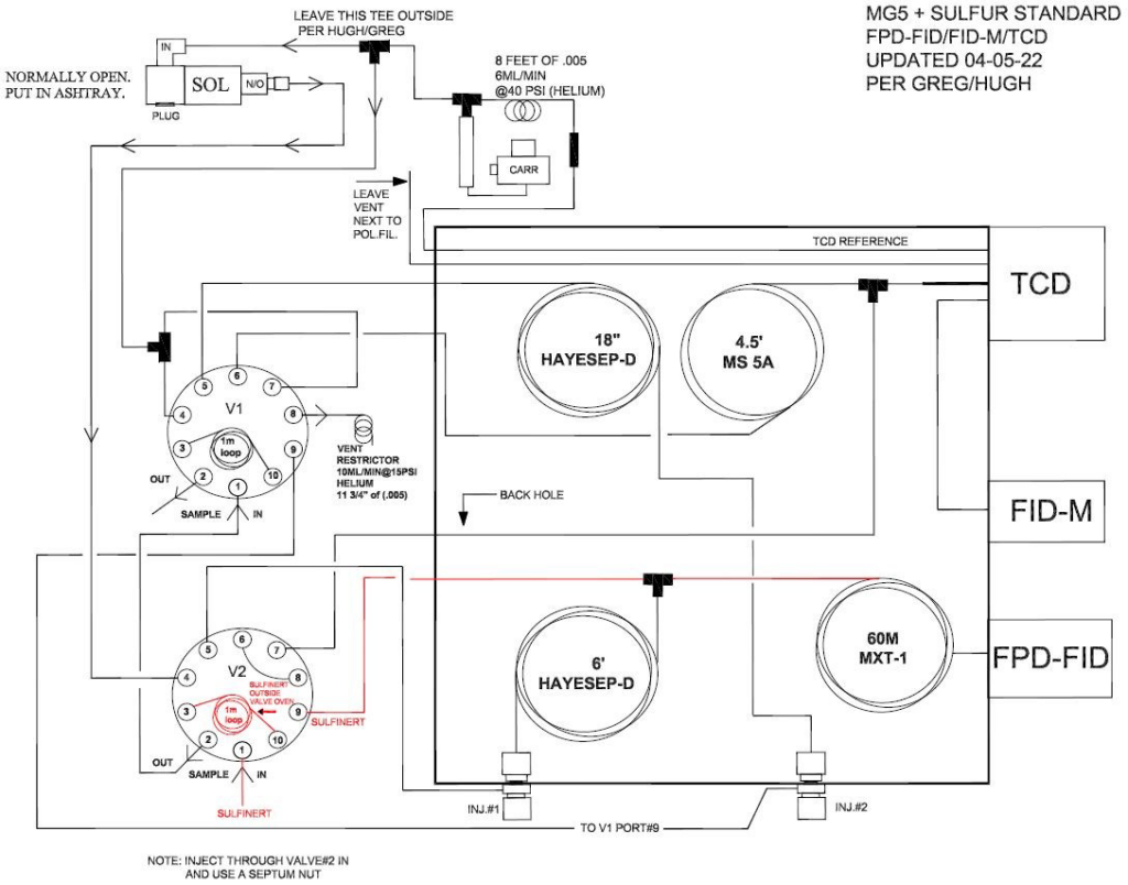
This picture shows an MG#5 with additional TCD, 10-Port Valve, backflush over precolumn, and extra carrier stream. This is needed if Oxygen and Hydrogen must be measured down to a low level of ppm in the same run. The best choice to measure Hydrogen is Argon as a carrier and Hydrogen as a carrier to measure Oxygen.


The schematic above shows the 4 steps in the MG#5 analysis after the sample has been loaded into the loop of each valve.
STEP 1: Valve 1 is turned to the INJECT position (Relay G on). The carrier gas pushes the sample out of the valve loop onto the 5-meter HayeSep D column. H2, O2, N2, CH4, and CO migrate through the 5-meter HayeSep D column very quickly and land on the 1-meter MS5A column.
STEP 2: Valve 1 is turned back to the LOAD position (Relay G off). Carrier gas continues to push the H2, O2, N2, CH4, and CO molecules through the MS5A column toward the detectors. Also, carrier gas backflushes any remaining molecules backward through the 5-meter HayeSep D column out to the vent (not through the detectors). The molecules which remain on the 5-meter column are CO2, Water, and C2 and higher hydrocarbons. These molecules would get stuck on the MS5A column if they were allowed onto the MS5A column. However, they easily backflush out of the HayeSep D.
STEP 3: Valve 2 is turned to the INJECT position (Relay F on). The carrier gas pushes the molecules in the loop of Valve 2 onto the 2-meter HayeSep D column in the “forward” direction. H2, O2, N2, and CO elute from the column very quickly as one peak, followed by the CH4 peak, the CO2, water, and the hydrocarbons from C2-C6.
STEP 4: At some point in the analysis Valve 2 is returned to the LOAD position. This reverse (back-flushes) the flow direction in the HayeSep D column. Any peaks which have not yet exited the HayeSep D column now back out of the column and into the detector. If for example, the analysis had no peaks after CO2 (or you did not care about any peak after CO2), then you would backflush after the CO2 peak. Any peaks remaining in the HayeSep D column would come out in a “lump”.
The following is a typical chromatogram of H2, O2, N2, CH4, CO, CO2, C2H2, C2H4 and C2H6 at 1% in Nitrogen.

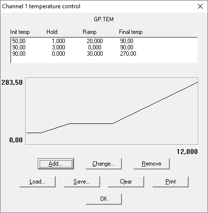
The screen on the right shows the oven temperature program used.
STEPS 1 and 2 occur while the column oven is at 50°C. After 1 minute, the column temperature increases to 90°C and stays there until after STEP 3. Then the column temperature increases to 270°C.
At some point, while the column temperature increases, STEP 4 occurs, backflushing any un-eluted molecules.
The channel 1 Event table is shown on the right. At time 0.05 Relay G turns on. This initiates STEP 1. At time 0.4, Relay G turns off. At time 4.00 Relay F turns on initiating STEP 3. At time 8.0 Relay F turns off backflushing the HayeSep D column to the detectors.
The exact times may change if the carrier flows rate changes or if a different carrier gas is used. The backflush time (STEP 4) especially may change depending on what molecules are in the sample.

MG#5 GC System’s Schematic:

8610-0570-2 MULTIPLE GAS ANALYZER #5 GC with TCD
8610-0571-2 MULTIPLE GAS ANALYZER #5 GC with TCD and FID-Methanizer
8610-0572-2 MULTIPLE GAS ANALYZER #5 GC with TCD and HID
8610-0573-2 MULTIPLE GAS ANALYZER #5 GC with Sulfur Analyzer